Programa Editor de Diseño
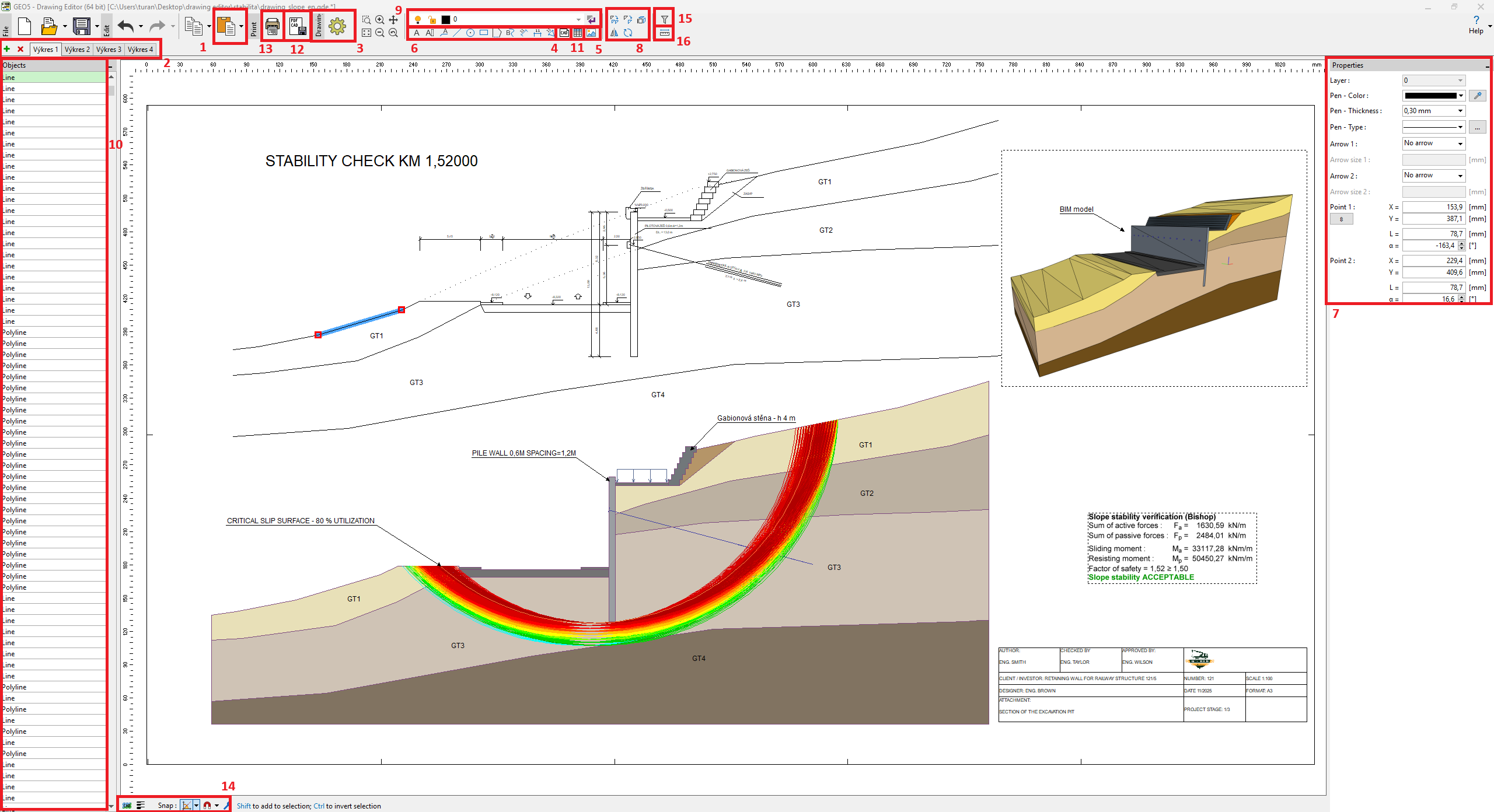
El Editor de Diseños se utiliza principalmente para editar y crear salidas gráficas avanzadas desde programas GEO5, pero también se puede utilizar como un programa CAD independiente.
Las vistas de todos los programas GEO5 se pueden insertar en el programa desde el portapapeles [1].
Un solo archivo puede contener varios gráficos [2], y cada dibujo tiene su propia configuración [3], por ejemplo, dimensiones, estilo, unidades.
Es posible importar archivos CAD (.dxf, .dwg, .dgn) o archivos IFC al dibujo [4]. Estos datos se insertan como bloques (a escala), que posteriormente pueden descomponerse en objetos individuales. También es posible importar imágenes (.jpeg, .jpg, .png, .gif, .tif, .tiff, .emf, .wmf) o archivos PDF [5].
Se pueden crear objetos de usuario [6]. Se pueden editar las propiedades de los objetos [7] y usar herramientas para modificarlos [8]. Los objetos se pueden colocar en diferentes capas [9]. Trabajar con objetos, herramientas y capas es prácticamente idéntico a la función "Notas" y se corresponde con los programas CAD estándar
La lista de objetos se muestra en el lado izquierdo de la ventana [10].Se pueden crear fácilmente tablas en cada dibujo, por ejemplo, para bloques de título [11].
El diseño final se puede exportar [12] o imprimir [13].
En la parte inferior de la ventana se encuentran ajustes especiales: tipo de selección, alternar el grosor de línea y ajustar la configuración a direcciones y objetos [14].Para seleccionar objetos de un tipo específico, se puede usar un filtro [15]. Además, es posible medir distancias lineales directamente [16].
 GEO5 Editor de Diseño